• Hello Guest, welcome to the initial stages of our new platform!
    You can find some additional information about where we are in the process of migrating the board and setting up our new software here

    Thank you for being a part of our community!

ABS Speedo Not working - removed from car and on bench

bugjam1999

Member
Joined
Aug 18, 2015
Hi all,

I just got a replacement cluster from a breaker, for a friend who installed an ABS axle in his 240 and now has a speedo that reads 4x too fast.

I said I’d check the cluster was working for him and replace the odometer gear etc. as I’ve done that a few times before.

Unfortunately, it doesn’t seem to be working. I used the instructions here:


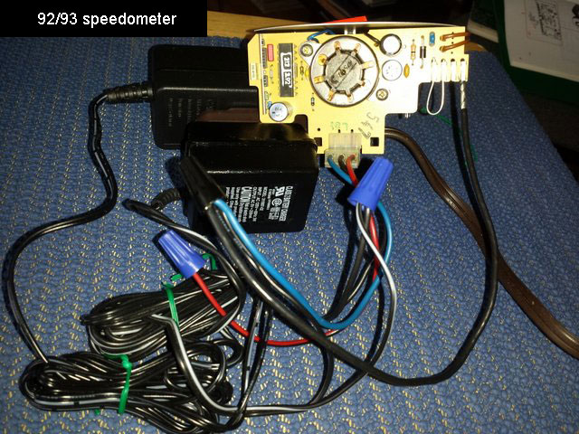
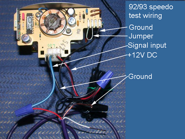
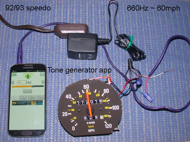
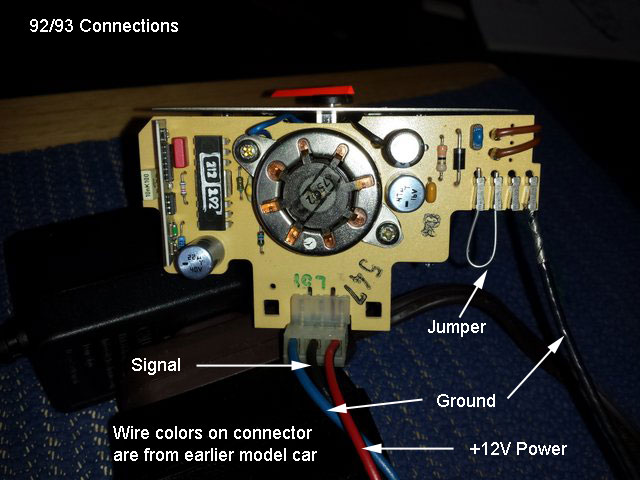
Like I’ve used several times before, connected up a 12v DC source and a 9v AC source to the back of the speedo (first in the cluster, then removed from the cluster with a jumper on the centre two pins) and both the needle and the odometer are motionless.

The original odometer gear is thankfully still in one piece, so there’s no bits of plastic jamming anything.

I checked visually for dry solder joints, and any components that looked like they’d overheated/failed etc and didn’t see anything obvious.

Any suggestions of what to try next?

Cheers
 

Attachments

  • IMG_0002.jpeg
    IMG_0002.jpeg
    883.3 KB · Views: 4
  • IMG_0003.jpeg
    IMG_0003.jpeg
    967.1 KB · Views: 4
  • IMG_0004.jpeg
    IMG_0004.jpeg
    784.9 KB · Views: 4
The order of the 3-pin edge connector changed from early (non-ABS) to later (ABS)
- non-ABS is: differential (green-white), ground (black), +12v (blue)
- ABS is: black (ground), differential (green-white), +12v (blue)

If you look near the connector pads on the PCB, you'll see: "+" [+12v], "G+" [diff], "G-" [gnd]

Non-abs is:
91speedo_pcb.jpg
 
Thanks for that- I was wiring it up incorrectly. Still not working- uh-oh, did I kill it by wiring it up incorrectly initially?

Cheers
 
Ok, tried testing again both inside the cluster and removed - I can see from the printed circuit board trace from the +12v feed and another printed ‘+’ sign on the board that it is the first two pins that need to be jumped (the clean flame trap link I posted above says the central two pins for an abs speedo which isn’t correct).

Unfortunately still nothing… will try again later.

That for help so far,

Cheers
 
Hmmm, I pulled out a scrap board and I think the the 4th pin, the one furthest from the motor, needs to be grounded too. The earlier non-ABS boards only have a single ground connection. The ABS boards have one ground connection on the 3-pin differential connector and one on the 4-pin cluster connector. They don't seem to be tied together on the speedo pcb itself.
 
Nice one- thanks for looking at a spare board. After adding the extra ground to that 4th pin the speedo needle started working and showing the expected 5mph. Is a consequence of this wiring setup for the abs clusters that an extra ground is needed to connect this cluster into a non-abs car?

The odometer doesn’t seem to be increasing, so I’ll need to investigate that further- if the needle is showing 5mph then the motor powering the odometer should be spinning as well- or is there some other weird connection I’ll need to make to test it? The odometer gear isn’t broken, so no issue there.

Thanks again for your help,

Cheers
 
Great, glad the speedo is working. I've never swapped non-ABS and ABS clusters. I'd expect that the extra speedo ground pin is handled by the cluster PCB, and hopefully the backside connectors are the same. The wires to the 3pin speedo connector need to be rearranged.

I'm not sure if the ABS speedo with the 4 pins can be fit into a non-ABS cluster - it would at least need an extra ground wire.

I looked at @cleanflametrap 's write up and realized there's ambiguity in the phrase "innermost two [pins]" - I think it means the 2 pins closest to the center of the board, not the 2 pins in the middle of the 4 pins.
 
I think if you've got a speedometer reading, all the connections are there for a working odometer, but 60 Hz input won't "spin" the odo of a 92/93 unit very fast. Be pretty slow stepping. And I believe there are other issues with the cluster wiring going from 92 to 89 aside from the speedometer.

speedo3257.jpg


speedo2187.jpg


speedo2196.jpg


speedo3214.jpg
 
Last edited:
Ok, update: I left the speedo connected for an hour and the odometer didn’t move at all, so I undid the two screws holding the motor on, swung the pcb and motor away from the speedo body and tried again - the motor was trying to spin but only sluggishly. I think the comment that 60hz is just a bit low is correct, so I’m assuming it’ll work when it’s in the car and above a speed of 5mph.

So having declared it working I cleaned it all, reset the mileage to match my friends mileage when his current odometer packed up and wrapped it ready for the courier.

I checked the cluster wiring pinouts on Dave Barton’s page, I think the only pins that change from year to year (well, at least for the later electronic speedos) are pins for od shift lights changing to speed signal outputs for the ecu and similar- nothing that’s of any concern for this car (m47, currently swapping to standalone) so I’m pretty confident that apart from swapping the two wires for the connector on the back of the speedo, everything else will work as it should.

Thanks for all the advice.

@cleanflametrap - thanks for writing up that speedo diagnostic page how ever long ago, I have directed loads of people to that page over the years.

Cheers
 
Ok, an update- the cluster is in the car and… the speedo doesn’t work.

If we leave the wiring as the (non-abs) car originally had, the rev counter, dash warning lights, fuel and temp gauges and dash illuminating lights all work, but the speedo doesn’t.

If we swap the diff sensor wire and the ground wire over, so the wiring is correct for the abs cluster, then nothing works on the dash.

So it seems the cluster needs a route to ground through the ground wire through the 3 pin plug on the back of the speedo for the cluster to power up correctly.

Open to suggestions of what to try next…
 
Well, I suppose there is that option- but as the abs cluster does work on the bench surely it’s possible to get it to work in the car…
Personally I would have modified the tone ring in the rear end, that's what I did in my 760. It wasn't worth re-engineering what Volvo changed 33 years ago
 
I tried to resize and line up the pictures of the 2 different speedo boards, but it's still hard to tell if the speedo PCB to cluster PCB pins line up.

speedo_board_differences.png

When you plug the later speedo into the earlier cluster, how do the 3 pins sticking out of the cluster PCB line up with the 4 sockets on the speedo PCB? If the first 3 pins line up, then you'll just need a jumper wire on the speedo PCB to connect the 4th socket to ground.
 
Annnnd…. A bit of user error and another change to the wiring required.

There was a miscommunication on wire colours between my friend and me, and he swapped the live and sensor wires, rather than the sensor and ground. Glad that didn’t immediately fry the diff sensor… anyway, fixed that mixup and it still didn’t work.

Then an idea- we swapped the wires to the diff and ground in the rear of the car and voila- all working now.

Thanks again for suggestions

Cheers
 
Thanks for looking- we swapped in the cluster complete not just the speedo, so there wasn’t an issue with the 3 vs 4 pins of the non-abs vs abs speedo pcbs.
 
Back
Top