• Hello Guest, welcome to the initial stages of our new platform!
    You can find some additional information about where we are in the process of migrating the board and setting up our new software here

    Thank you for being a part of our community!

Vehicle speed sensor signal to Jetronic

theknave

New member
Joined
Mar 25, 2014
Location
Seattle
Hey there.

1990 240 DL, stock b230f, open diff.

I tried to search for something on this, but I couldn't find anything quickly.

What I'm looking for is a circuit diagram or something of that sort so I can send the signal the Jetronic wants from the PMG speed sensor to the Jetronic.

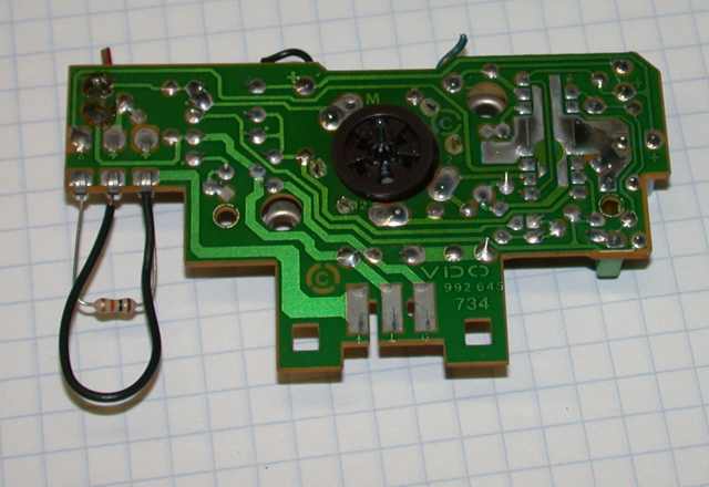
As an alternative, I have the original circuit boards from my original Volvo speedo, if all else fails perhaps I can use those. If so, anyone know what would need to be connected in that case? I'm currently using an aftermarket speedo.

Thanks!
 
Thanks for that first link - it has lots of good general information, but I'm not sure it has the diagram that's closer to...

...the diagram in that second link.

I've seen that one before. So, if I'm to build my own signal conditioner, it seems like I'm going to need that ITT logic chip, along with those capacitors, resistors and various things?

I think I'll try using the original speedo boards first, see if doing so gets the 3-1-1 code to go away and the idle to drop.


That being said, I have the following questions:

1. Can I just splice off my PMG signal (going to my current aftermarket speedo) to the "G" in the cleanflametrap diagram? and the speed signal ground wire to "(down arrow)" in the cleanflametrap diagram? then go from "A" in that diagram to pin 34 in the LH2.4? Where exactly is "A" on the original speedo?

2. Is step 1. above enough, or do I need to also provide the 12v battery voltage?
 
Actually, I think I see where "A" is here:

speed11.jpg


I'm thinking it's the farthest left 'pin socket', where that resistor is tied in and jumps back to the pin socket two to the right of it.
 
Actually, I think I see where "A" is here:

speed11.jpg


I'm thinking it's the farthest left 'pin socket', where that resistor is tied in and jumps back to the pin socket two to the right of it.

Follow the trace to the pin on the 2115. That's what provides your VSS to the ECU. It is an open collector, so that's why I have a pullup resistor stuffed in the socket; so I can observe the signal with the scope. You're on the right track, but be sure to use a good board, because this is the pin that gets ruined when someone plugs the tach wire on the double spade. :nod:
 
Ok... Do I need a pull up resistor as well?

Is there a way can test proper output with a multimeter?

Also, is it ok to splice a wire from A on that board to the blue/black wire past the connector on the back of the instrument cluster? I noticed in a separate wiring diagram that the speedo seems to connect to the cruise control unit just before the round connector.

Thanks!
 
Ok, so I put ignition switched battery voltage to the "+" on the circuit and went along the various paths, verifying battery voltage until the first resistor with a voltmeter. I was able to read anywhere from 10 to 11.8 v at various spots in the circuit.

The output at pin "A" was 10.53 or so. Is this a good reading? All I did was turn the ignition to "ON", the speed signal was not hooked up to the circuit, yet.
 
Back
Top