• Hello Guest, welcome to the initial stages of our new platform!
    You can find some additional information about where we are in the process of migrating the board and setting up our new software here

    Thank you for being a part of our community!

Bad Banana in SoCal

I found the of the new polyurethane bushings from RockAuto for the A/C compressor in the mailbox when I came home from work this evening. So pressing (squeezing really) them into the mount bracket seemed like a good idea. I used a length of threaded rod and a couple of nuts to pull them into their respective sockets. I wiped a light coating of petroleum jelly on the inside of the sockets to make them slide in easier and also to provide a little bit of corrosion protection to the bracket longer term. I had painted the new brackets 2 days ago and baked them for about 90 minutes at 300F after my lovely wife was asleep. It's a good thing that it was cool enough the last couple of days to have all of the downstairs windows and doors open for ventilation!

Here's the finished compressor bracket:
50303835172_97f943eb05_b.jpg


I also put a captive slip-on nut plate on the painted receiver-drier bracket. It provides a blind nut for the single screw that secures the receiver-drier clamp. That's critical as it is in a tight spot under the air filter canister. It would not be fun to try to put a nut on the back side of that screw!

Here's the finished receiver-drier bracket:
50303835167_9db896e1e2_b.jpg


And in-situ:
50303833367_5086462c7a_b.jpg


Installation of the finished receiver-drier bracket with my old unit looks like it may work out OK for routing the plumbing:
50303683476_b231443c22_b.jpg


I plan to use a 90deg fitting pointed down and route hose to the existing hole near the bottom of the core support to connect up to the condenser output port. Hopefully I can use a 45deg fitting and run the receiver-drier outlet hose along the fender inner panel to the existing hole in the firewall and connect up to the expansion valve on the HVAC module under the dash.

Over on the engine I fitted up the new compressor mount and Adel clamped the fuel lines in place:
50303834687_525b16ce39_b.jpg


There is just enough room for the new hard lines to clear the lower edge of the compressor mount bracket and the upper edge of the timing gear cover / block.
50303683401_d29b00ddce_b.jpg


By just enough room I mean that I can put my finger in between the fuel lines and the surrounding structures. Hopefully the clamps provide sufficient locating support so that the hard lines don't move around and rub on the vibrating engine hardware. I've added a fuel line sleeve around each of the tubes where they are closest to the block and mount bracket as a precaution.

Next up is fitting the compressor for final drive belt sizing.
 
Looks clean and very well executed.

Did you catch that your vent hose from your filler cap has a deep cut in it ?
 
Looks clean and very well executed.

Did you catch that your vent hose from your filler cap has a deep cut in it ?

Thank you Matt. Yes I did and I have ordered up a replacement. I should have it tomorrow morning. I'm assuming that the Phillips head screws in the oil filler cap go into the breather h
ose to keep it in place. I guess I'll figure that out in the morning....


Love the 145! Very professional work. Keep it up!

Thank you very much Ian.


Today was not very productive. I didn't make it into the shop at all. This morning on my way out I noticed some water at the corner of the garage door. There is a hose bib and hose reel right there so I figured that someone left the hose on over night. But no, that would be too easy, the hose was off. So I opened up the garage door to find water along the east wall back to the south corner where the water heater and sink are located. I crawled under the sink and discovered that the water heater was not leaking. Thank goodness!!! But the angle stop that connects the sink faucet to the wall hot water pipe was leaking a very steady drip. And when I touched it to turn off the water all hell broke loose. I felt like I was in Oklahoma in the 1900s and had just discovered oil. It was a gusher.

As I was turning off the water main to the house and garage my lovely bride came out and asked me if I was messing about with the power? You guessed it, the power went out. And a short while later we lost terrestrial phone service too. A great start to the day.

So after a trip to our local plumbing supply house I was able to source new 1/4 turn angle stops, flex hoses and a new faucet assembly for the sink (A little bit of scope creep there, did you catch that? the new faucet has a goose neck that will make filling up a 5 gallon pail in the sink much easier.). By around 1:00pm I had the plumbing remedied. Then after eating lunch it was going on 2:00 so I just bagged it for working today. By about 4:00 the power was back on. And around 7:00 we had phone and internet working again. It was only about 95F today so it was actually a pretty awesome day for this trifecta to have happened. Really. We're expecting 110F tomorrow and Sunday so it'll be nice to have the A/C working in the house.


After lunch, because I wasn't going in to work, and since the power was back on, I decided to hang the a/c compressor on the engine. It has turned out OK, but not as nice as I would like. The compressor is about 1/2" closer to the brake boost vacuum canister than I would like. There is room for the pressure and suction hoses to clear but it is tighter than I want it to be.

The compressor installed:
50306189128_169c4fcb5f_b.jpg


So I think that I will cut a new pair of adjuster brackets for the compressor that will allow it to rotate tight up against the mounting bracket, or as close as possible anyway. That will be a nice little project for next week. In the mean time this weekend, if it's not too hot outside to work comfortably, I can work on the electrical for the fan and compressor and plumbing routing for the a/c lines.
 
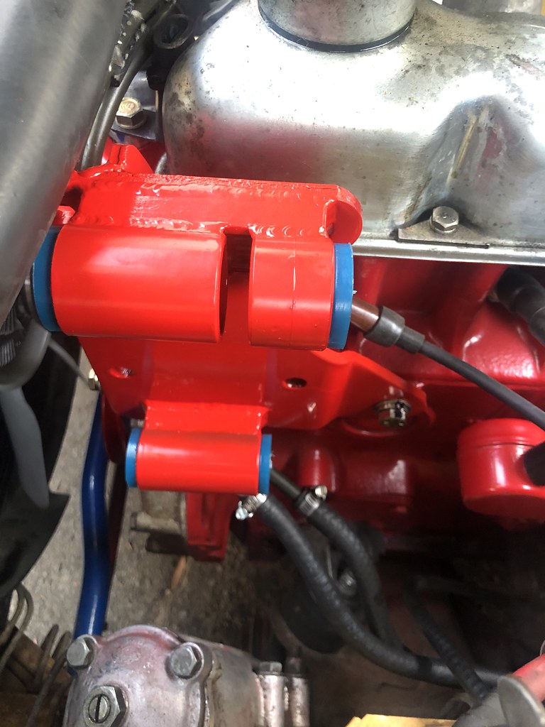
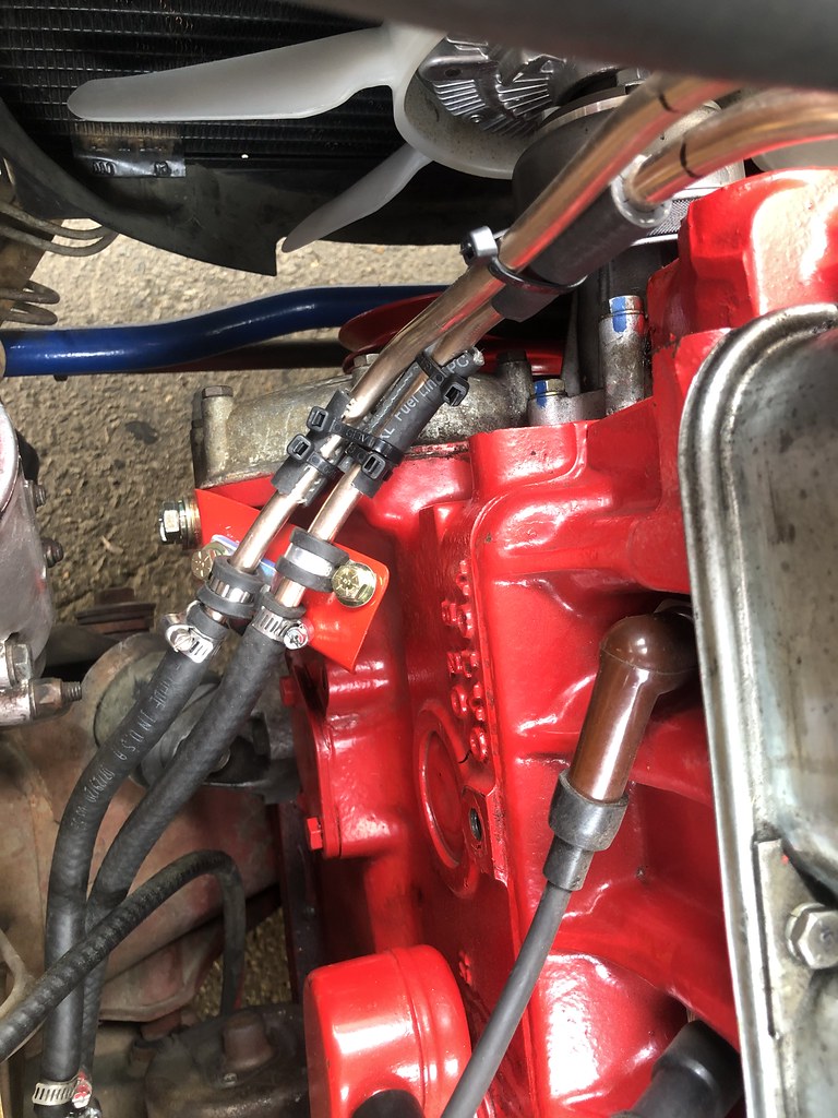
I decided that I was not entirely happy with the compressor clearance to the power brake vacuum boost canister. So this morning I removed the compressor mount bracket to start working on new flange tabs that mate the compressor to the mount bracket. Upon removal of the compressor and mount bracket I found some witness marks on the new fuel hard lines. I put my finger under the mount bracket and could feel clearance all around the tubes. So maybe the witness marks are simply the result of fuel line contact during bracket installation. But I want to be sure. So some insurance (scope creep?) is in order in the form of a support bracket for the fuel lines to make sure that they can't move around and come into contact with the bracket, block or compressor which would lead to fuel line failure. This would most definitely not be a good thing!

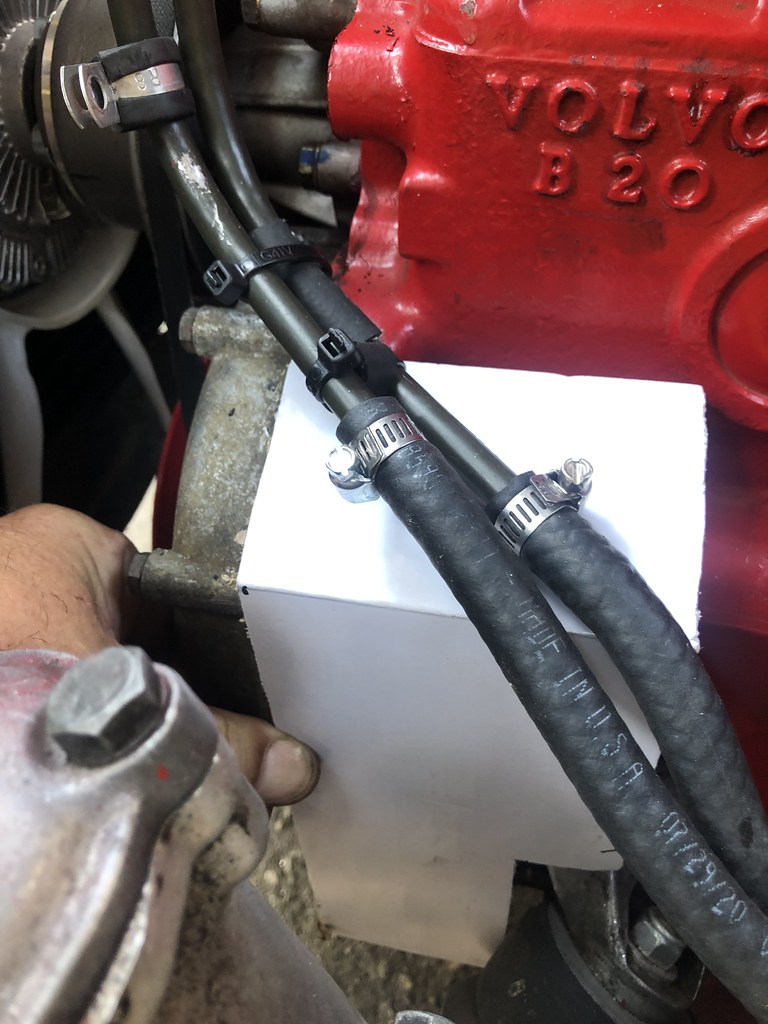
Shiny scratches are visible on the left most fuel line. The extra bit of fuel hose on the upper line is there to act as an anti-chafe cushion between the two hard lines:
50313629252_db1455fa5f_b.jpg


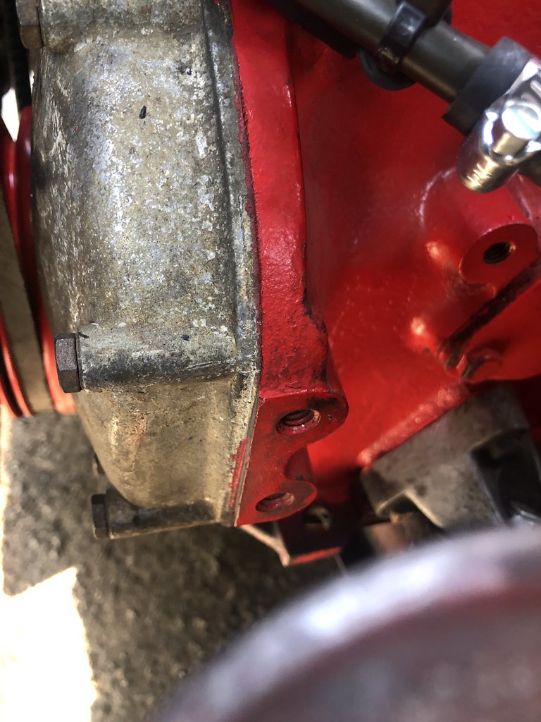
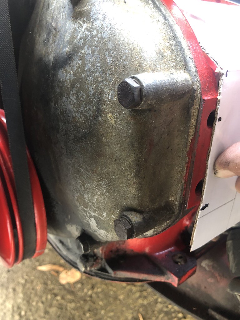
Looking at the side of the engine block showed a couple of existing drilled and 3/8" coarse thread tapped holes conveniently located for mounting a fuel line support bracket on the side of the timing gear case:
50313780827_075ec06186_b.jpg


It's difficult to reach down in that area to get a good measurement for the hole spacing. Not to worry, I'll be designing this new bracket using my trusty old CAD system. That's Cardboard Aided Design for you non-technical types. So I got out my tool set:
50313784712_06fde7801b_b.jpg


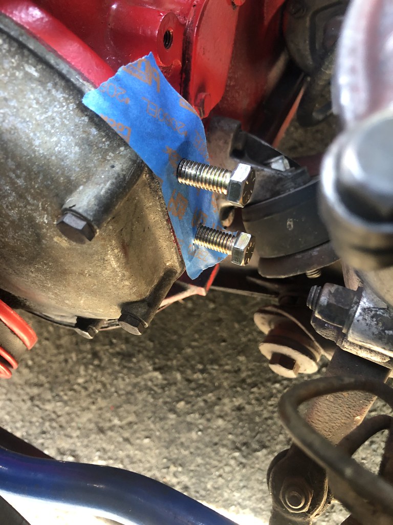
In order to capture the hole pattern / spacing I applied a strip of tape to the side of the block and then pushed a couple of screws thru the tape to punch holes in the tape:
50312869223_b1f7ee8a0f_b.jpg


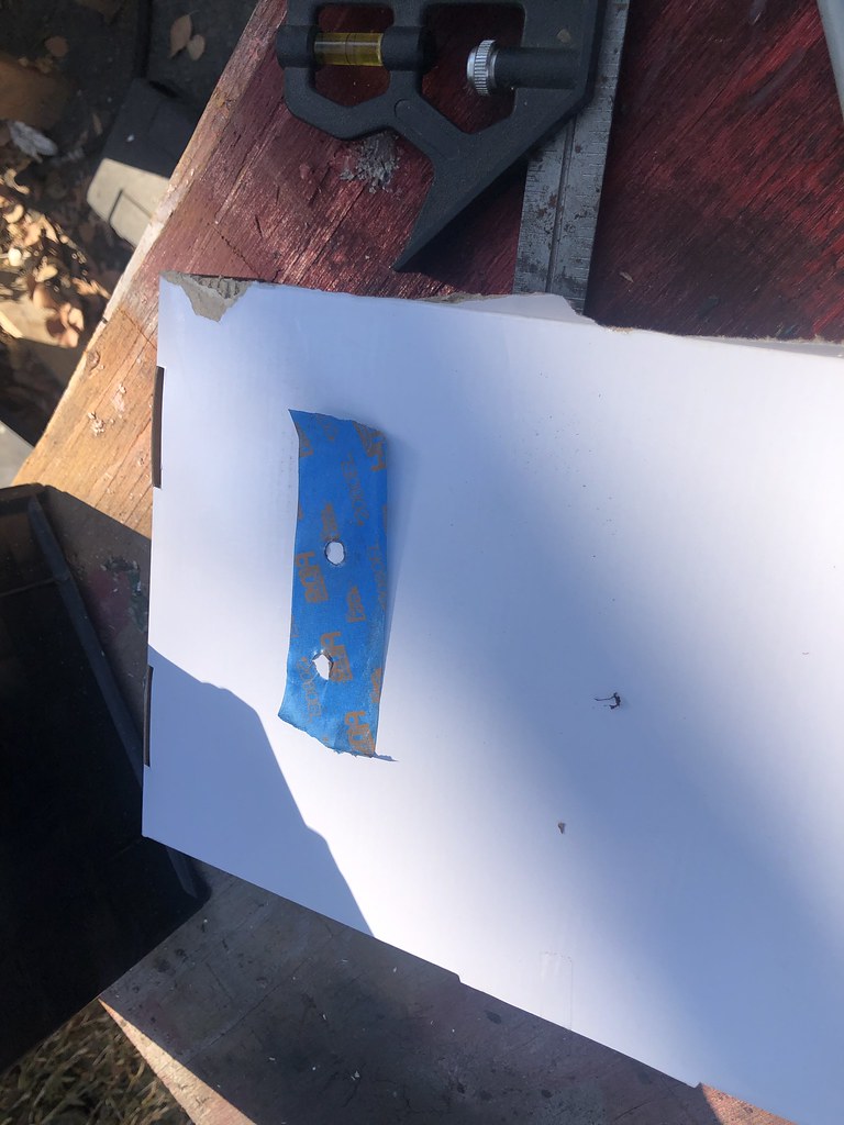
As you can see, the holes aren't very pretty making it difficult to get accurate dimensions from the tape:
50313451756_49ab1161e5_b.jpg


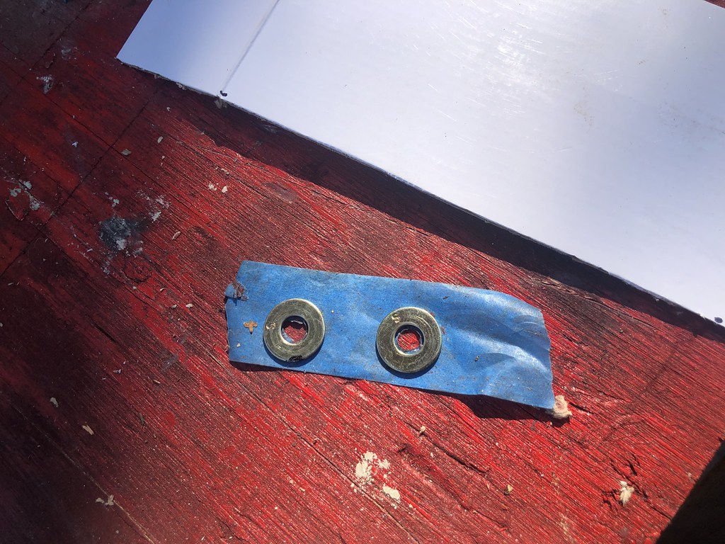
Not to worry though, a couple of washers will stick right to the tape:
50313663407_8cae59c830_b.jpg


Followed by a quick fit check back on the side of the block. Now Press the tape down firmly on the washers to locate them securely.
50313661562_40e1a7239a_b.jpg


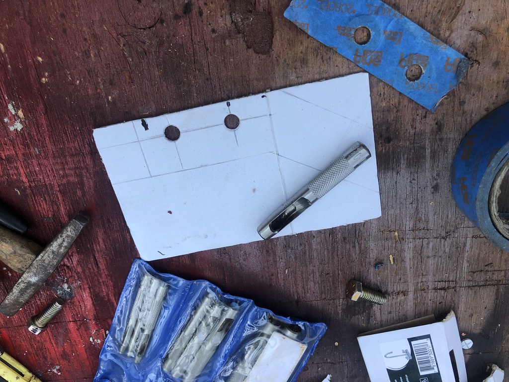
Then remove the tape and washers from the block and return to the work bench. At the work bench lay another piece of tape over the opposite (sticky) side of the tape and the washers are now securely captured in the proper relationship to the holes in the side of the block.
50312818558_9a289130c6_b.jpg


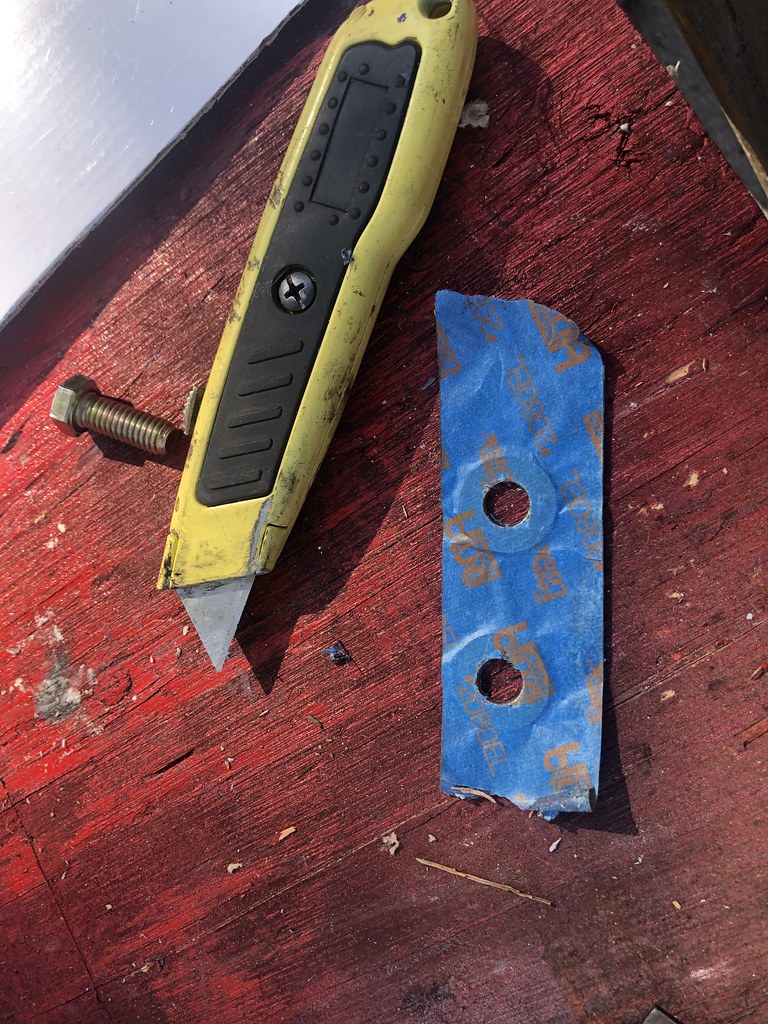
Next take your trusty razor knife or other suitable implement of destruction and open up the holes using the washers as a guide. There you have an accurate hole pattern template:
50313539086_e0e07db769_b.jpg


The next step is to cut a bit of cardboard from the scrap cardboard box that I had laying about (remnant of the garage faucet replacement of a couple of days ago). Review of the shape of the cardboard scrap before rough cutting to shape revealed a conveniently placed fold in the cardboard. Holding the cardboard in place allows marking to start to get a feel for the shape of the new fuel line support bracket:
50312866758_590b768a28_b.jpg


Back on the work bench the basic outlines of the bracket are marked with a pencil. I use a pencil for this as opposed to a magic marker as it is easier to erase when I screw it up!
50313782977_75f8885f02_b.jpg


Moving back to the block it's time to mark the locations of one of the hole centers and the bottom edge of the new bracket. This time with a Sharpie as it is easier to get a defined point with the pen in these relatively confined spaces than it is with a pencil:
50313781842_eb80056c5c_b.jpg


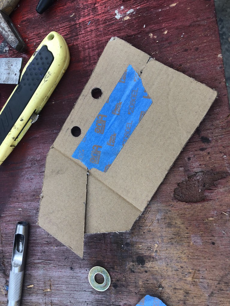
Back on the work bench it is now time to use the tape template to layout and punch the mounting holes in the cardboard:
50313778992_a2bcdabfc0_b.jpg


And then cut the cardboard into shape:
50313777267_ed8631f8d5_b.jpg


Then move back to the engine for fit check and marking. A couple of Adel clamps will be screwed to the new bracket to secure the fuel lines.:
50313806652_74d2c82169_b.jpg


Since the engine vibrates during operation the cantilevered tab on the bracket will likely act like a tuning fork at some point. So a bit of russeting is required to make sure that it doesn't fatigue over time. Back on the work bench the cardboard cut piece just removed is of convenient size and shape to form the gusset. A quick bit of taping on the back side makes the two pieces whole again:
50313806287_4978ac7617_b.jpg


And tape applied to the outside of the bracket makes it sufficiently strong to maintain position:
50312960963_2bbfba00dd_b.jpg


This added gusset piece is not yet in the proper shape for the new bracket bend configuration. Back on the engine it's time to mark the gusset for cardboard trim to final shape and return to the work bench for trim subsequently applying tape to both sides at the top of the pattern:
50313627336_d3bcaa6bc2_b.jpg


Another fit check shows that the tab at the top of the bracket is not quite long enough to fit screws for the Adel clamps:
50313803552_70c33ef910_b.jpg


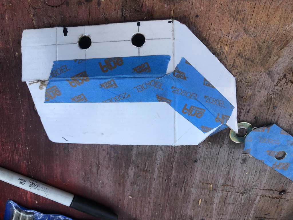
Not to worry though as we have more cardboard and tape at our disposal. Here is the bracket taking shape with extra card stock added and holes punched for securing the Adel clamps:
50313625896_172f75ce97_b.jpg


One last fit check is in order:
50313624786_698c709dff_b.jpg


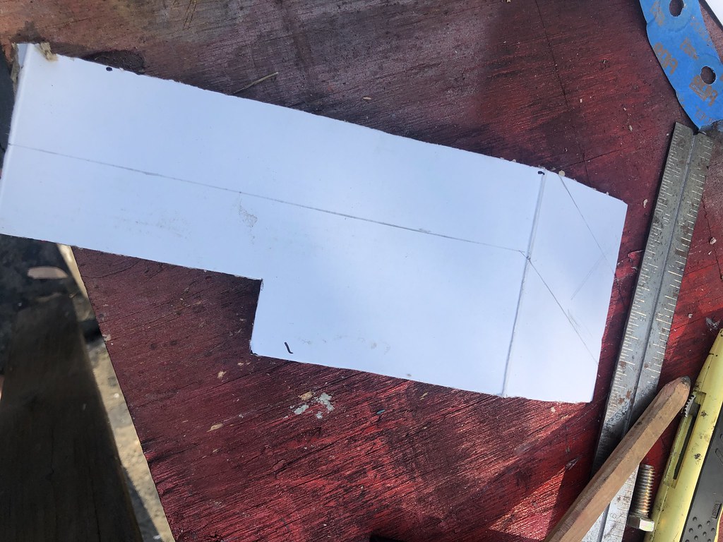
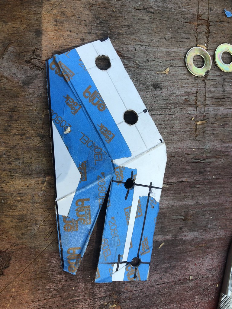
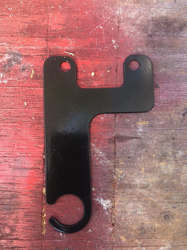
And then cut the tape free as required to lay the cardboard pattern flat so that it can be traced out later onto a piece of sheet steel:
50313800962_65bc953eb9_b.jpg


I think the new support bracket will do its job nicely and it was a good example of how to effectively utilize CAD techniques.

At this point I decided to call it a day for a couple of reasons:
1) My lovely bride said it was approaching noon and offered to make some lunch if I wanted to come inside.
And.
2) It was getting pretty warm out in the sun in the driveway:
50313624001_16ff192454_b.jpg
 
As I was turning off the water main to the house and garage my lovely bride came out and asked me if I was messing about with the power? You guessed it, the power went out. And a short while later we lost terrestrial phone service too. A great start to the day.

So after a trip to our local plumbing supply house I was able to source new 1/4 turn angle stops, flex hoses and a new faucet assembly for the sink (A little bit of scope creep there, did you catch that?

Of course. I was fully expecting to see all new copper piping and maybe even a new garage roof before the end of the weekend....

The next step is to cut a bit of cardboard from the scrap cardboard box that I had laying about (remnant of the garage faucet replacement of a couple of days ago).

See? It wasn't overkill, just preparation. :nod:
 
I made the bracket today and tried my hand at summarizing the fabrication via video:
<iframe src="https://player.vimeo.com/video/457164800" width="640" height="360" frameborder="0" allow="autoplay; fullscreen" allowfullscreen></iframe>

I've applied the paint and hope to install it this weekend.
 
I got some time this afternoon to install the fuel line support bracket, the compressor mount and the compressor. I also made another set of fuel lines out of copper nickel brake line instead of steel. It is much easier to bend and will accept a tighter radius as well which made for improved clearance at the bottom of the compressor mount bracket.

Here's a pic of the new fuel line support and revised fuel lines all installed. I have used some extra fuel line to act as anti-chafe to ensure that the fuel lines don't rub together:
50339899512_b87bdb32f6_b.jpg


And with the compressor neatly tucked into its new home:
50339055158_b15dfa2a12_b.jpg


Note: I tightened up the adjuster screws after this pic was taken.

Now it's time to fab a set of hoses and then connect up the E-fan, compressor clutch and over-pressure safety switch. Oh yeah, I also have to size a drive belt for the compressor.
 
Brilliant idea with the painters tape and washers. I skimmed through the last few posts, are you powder coating or spray? It all looks fantastic.
 
Brilliant idea with the painters tape and washers. I skimmed through the last few posts, are you powder coating or spray? It all looks fantastic.

Thank you for the kind words. I?ve been doing the washer and tape thing since I was a kid; back in my slot car days.

I am rattle can spray painting with etching primer and Rustoleum. Before painting I?m sandblasting wherever possible. I.e. if it will fit in my blast cabinet. I prep all parts with acetone immediately before painting to ensure any lingering oil residue is removed. Paint consists of light coat of primer and 2 coats of color. After the finish coat of paint cures sufficiently to be able to handle I bake at 325F for 30 minutes. At assembly time I try to keep my hands clean and pre-fitting parts before painting helps to assure that they go together w/o interference. The resultant finish has proven to be quite durable.
 
Does anybody know whether or not these two plugged holes have threaded nut plates behind them on my '73 145? I'm referring to the 2 plastic plugs on the cowl between the windshield washer reservoir/pump and the wiper motor, circled in the pic below:
50347174267_dbd3daa600_b.jpg


They are pretty well aged and I think that I would destroy the plugs by attempting to remove them. If they are threaded I can use them to provide anchor points for a future A/C hose support.
 
Unfortunately, no; they don't.

Thanks for the info. Not to worry, there are plenty of other existing holes, screws and bolts on the firewall to use to secure the A/C return hose from the evaporator to the compressor. Thanks to your response I have gone in another direction that will work out well I think. At least I hope that it does.

Your progress on this car is quite awesome, and I'm following with interest.

Thank you very much.


I had a bit of time at the shop this afternoon so I took advantage of the opportunity and made a plan for the A/C hose routing. With that in mind I made a few new parts, some brackets and hard lines:
50377284981_f551d5d64b_b.jpg


Top to bottom they are:
1) Support bracket for the return hose to the Compressor from the Evaporator
2) Aluminum hard line from the Receiver-Drier to the Evaporator (to go through the cowl)
3) Steel hard line from the Compressor to the Condenser (to route around the steering gearbox and under the battery tray))
4) Aluminum hard line from the Receiver-Drier to the Evaporator (to get around the air cleaner
5) Aluminum hardline from the Evaporator to the Compressor (to exit the cowl)
6) Revised E-fan lower mount brackets

With the routing laid out I can now order the proper fittings. I'll be placing a parts order with Cold Hose in the morning. Once received I can move on to get the hoses final-fitted (hopefully), crimped and installed.

With any luck I'll have A/C working by wintertime.
 
I spent a little time working on the Banana today. I placed my parts order with Cold Hose this morning. I hope that I got everything that I need because they're all the way on the other side of the country from SoCal. I also installed the new support bracket that attaches to the cowl and will keep the A/C return line from the evaporator back to the compressor properly located and not rubbing on a bunch of other stuff. A nice by-product is that the stiffening flange on the back side of the bracket also provides a convenient little cable tray area to clean up and more effectively control all of the wires that traverse the cowl from the driver's to passenger side of the engine bay. I added a few holes to the bracket to allow convenient placement of cable ties in the future.

Here is the new support bracket installed:
50380917882_8cb039cbcc_b.jpg


Since the new A/C compressor is very close to the brake master cylinder I already have re-routed the positive battery cable to run a bit further down so that there is no risk of contact with the compressor. I decided that a new support / guide bracket was in order to replace the original Volvo bracket. The new bracket routes the starter wire below the power brake vacuum reservoir instead of along side it.

Here is the new starter wire support / guide bracket:
50380896262_8682e0e9d1_b.jpg


And now with a proper grommet to better insulate the wire from chafing damage:
50380019218_23d650ac35_b.jpg


I will make a new battery-to-starter motor lead wire in the next couple of days as the original one that is still functioning could stand a fresh connector at the battery end. I'll make a fresh ground lead at that time as well. You know, as long as I am in there..... Haha.
 
It's been pretty hectic around here for the past few weeks, leaving zero time to play with the Bad Banana. However that changed this past weekend as I needed to do a bit of preparation / maintenance for a short get-away drive up to the Central Coast area with a few buddies. Nothing too major needed attention except for a new fuel pump. The original unit has been acting up a bit over the summer, requiring a light wrap with a massive object to bring it to life every now and then. While it never rains here in SoCal, it did, of course, rain this past weekend when I needed to be outside to change the fuel pump. Good thing that it was relatively dry on the creeper under the Banana! Haha.

The OEM Bosh fuel pump in-situ:
50585813211_88c956f9e2_b.jpg


Since the OEM Bosch pump is no longer available I searched the interweb a couple of weeks back and found a suitable substitute in terms of pressure and flow rate to support the D-Jet EFI system. I went to the Rockauto website and looked up their recommended replacement pump, a Delphi p/n FD0011 at $104 plus shipping. Review of the Info tool on the Rockauto website showed the Delphi pump to be rated at 58PSI and 32GPM. I did a bit of searching and came up with a less expensive option with nearly identical specifications. I chose a Powerco p/n E8445 rated at 45 - 65PSI and 35GPM for a much more reasonable $64.92 delivered. It came with appropriate 5/16" diameter barb fittings, screw lug crimp-on electrical connectors and a pair of mounting clamps. I tossed the spring hose clamps.

I had to fab a mounting plate to interface the new pump to the Volvo's pair of vibration isolator mounts as well as source a 1/2" - 5/16" barb hose adapter (not shown in the bench top pic) to neck down the fuel tank feed hose to the new pump's 5/16" inlet as well. I also replaced the factory fuel pump connector with a 2-pin Delphi Weather Pack connector on both the pump and the Volvo's chassis harness, taking care to install the sockets on the powered chassis side harness and pins on the pump side of the connection. While I wanted to route the cable above the hoses (It's always best practice to route wiring above fluids, specially flammable ones) there just wasn't room to make that a reality in the tight confines of the factory pump location.

Here's the new rig on the bench prior to installation:
50585933852_f7c0135a94_b.jpg


The extra hose tie wrapped to the fuel feed hose is to isolate the U-bend from the edge flange of the fuel tank which is in ver close proximity as well as to provide a bit of anti-kink protection on the relatively tight radius of the required hose loop.

And here is the new pump installed prior to re-fitting the factory splash guard plate underneath:
50585067493_fccbd096ff_b.jpg


I have road tested the installation for the past 3 days to the tune of about 130 miles and all is working properly --- I hope that this substitute pump turns out to be a winner in terms of reliability.

Tomorrow afternoon I'm gonna knock off work mid-day to get ready for an early Friday morning start on our back country drive up the coast. We plan to spend a couple of nights in Cambria, a night in Solvang and then home to San Diego. We're targeting several great roads on the drive including, but not limited to, Cerro Noroeste Road, Prefumo Canyon and See Canyon Roads, Old Creek Road, Santa Rosa Creek Road, Hwy 1, Nacimiento - Fergusson Road, Tepusquet Road, Foxen Canyon Road, etc. The cars on the trip are a '63 Porsche 356, a '73 Pantera, a '69 Alfa Super and the Bad Banana. A nice little Euro-centric international group.

This will be the first time I've been out on a drive since returning from an epic adventure drive down the length of the Baja Peninsula to La Paz, Mexico back at the end of February / beginning of March. We'll be practicing social distancing, wearing masks and each of us solo in our cars, albeit with 2-way radios. We're thinking that traveling solo and carrying food and drink in the cars will be less risky than venturing out to the grocery store. At least we hope that is the case! At any rate we're going and thinking that this will be a great break before the winter holidays. And my first real opportunity to take the Bad Banana on a spirited long distance drive.
 
Last edited:
Lots of projects going on here presently. Upon return from our weekend holiday yesterday I had a free evening and reassembled my Ford T-9 transmission that goes into one of our other cars with significant assistance from Lucy. Given that some have used this gearbox on early Volvos I thought that there might be some interest here in this project so I made a brief video summary of the reassembly highlights:

<iframe src="https://player.vimeo.com/video/480678107" width="640" height="360" frameborder="0" allow="autoplay; fullscreen" allowfullscreen></iframe>


How did it go? I totally would have been down with meeting up. Should check these posts more often!

I'm sorry that we missed you. Maybe we can meet up next time. As for how the trip went, I think that this video will give you a better feel for Day 1 over my feeble attempts to convey the experience through words:

<iframe src="https://player.vimeo.com/video/481061193" width="640" height="360" frameborder="0" allow="autoplay; fullscreen" allowfullscreen></iframe>
 
Last edited:
Ah very nice. All my stomping grounds! (Born and raised in SLO, lived in this county my whole life). Thanks for the insight on the T9, have always been curious about those.
 
Back
Top