• Hello Guest, welcome to the initial stages of our new platform!
    You can find some additional information about where we are in the process of migrating the board and setting up our new software here

    Thank you for being a part of our community!

Official 245 T6 Thread- Quest for the Ultimate 265

Kildea has managed to control the VVT on his T6 in a rudimentary way with the MS second injector bank.

I don't think building a stand alone VVT control box would be a monumental task.
 
I know Kildea felt there was one, but I have played with cam timing on this thing quite a bit on the dyno. And I haven't seen much potential for perfomance gains at least with my current setup - but all my power is way up in the revs.

The exhaust cam is currently advanced to give best spool/bottom end. If I advance it more I stop gaining spool and lose power everywhere.

Retarding it moves the power around a bit, it maybe picks up a bit of midrange, but the car doesn't really make more power, and spool/bottom end is reduced significantly.

If having the cam advanced as it currently is to maximize spool was hurting top end power, then I might worry about it, but I have top end coming out my ass.

IMO if you want to do VVT, you need to modify some cams to work with it too, the T6 cams are really wimpy.

The 960 cams really woke my motor up - I wouldn't trade them for T6 cams even with proper VVT control. That's like the whiteblock equivalent of trading a K cam for a VVT controlled T cam. :lol:

My motor also isn't set up for intake cam VVT. If one were to do VVT I would suggest controlling the intake cam or both of course. I could realize some gains with VVT intake control from what I've seen.


Another consideration though I guess is that my setup is pretty laggy- since I make all my power from 5000-7500 so it might be that the cam timing changes that affect power below those rpms are going largely unnoticed.

I'm going to go 1 or maybe even 2 sizes smaller on the turbine housing next year. Might opinion might change then.

But honestly if I could move the boost curve down 1000rpm this thing would just be an animal. If I can move the curve down that far and still make 450-500whp the project will be pretty much complete to me. :nod:
 
That is good info Is there a video of this car somewhere I want to hear what it sounds like. I am on the fence on what engine to use for my Bertone 5 Turbo or 6 Turbo. Also what trans are you using I am going to be following your thread.
 
Here's a video of Justin's 242 T6: http://www.youtube.com/watch?v=mCYhOh7gmzs

He was fighting some MS issues at the time, so he couldn't really get on it, but it should give you an idea. It really sounds amazing. The 5 is only better in the sense that it's smaller and 1/5th cheaper to build, otherwise the 6 is better in every way. More displacement, much easier swap, easier EMS setup, pulse paired manifolding, better balance, etc.
 
Couple vids of mine.


<object width="425" height="344"><param name="movie" value="http://www.youtube.com/v/m0T4VX0c7Hs&color1=0xb1b1b1&color2=0xcfcfcf&hl=en_US&feature=player_embedded&fs=1"></param><param name="allowFullScreen" value="true"></param><param name="allowScriptAccess" value="always"></param><embed src="http://www.youtube.com/v/m0T4VX0c7Hs&color1=0xb1b1b1&color2=0xcfcfcf&hl=en_US&feature=player_embedded&fs=1" type="application/x-shockwave-flash" allowfullscreen="true" allowScriptAccess="always" width="425" height="344"></embed></object>
 
PC010229.jpg


PC230231.jpg


PC230232.jpg


A few pieces to finish welding, standoffs for the fuel rail, mod the rail for AN fittings, and bracket for the throttle body cable and she's done.

Just a fuel pump + lines, breather system, intercooler bracket and revised piping, 707 pressure plate to do other than that.

Plan is to dump the H beams into a fresh motor probably in february and hit the dyno in March. Should make similar numbers to the "other" Kennyses cars, but without race fuel or spray. :oogle:
 
That is shaping up pretty good. Looks like it is going to be quite awkward to get to the head fixings on the underside though? There is more space on your 245 than I have, but the breather , starter motor and brake servo still get right in the way.

What have you done at the thermostat housing?... I can't make it out too well in the photos. Couldn't the stock housing be shortened/reworked/ a different angled top fitted to clear and avoid the swan neck if it isn't needed for clearance, or has using a top exit allowed the use of the stock lower housing and thermostat?
 
^ The T6 motors have the thermostats on the front of the motor, you can just make out the housing there just under the cam gears.

Where the thermostat is on the earlier motors, the T6 just has a hose takeoff bolted to the head which is a bit smaller, leaving more room for the intake manifold/whatever.
 
There's lots of space in there for whatever tstat housing actually (If i did have one ther) - the swan neck was actually needed to clear the power steering reservoir before I relocated the pump to below the alternator. As was said there's no thermostat housing there though in my case, it's just there for the upper rad hose to attach to. I''m looking forward to getting rid of it, it'll clean things up some more.


You can't tell from those pics but access under the manifold is fantastic now. it was a nightmare before with the T6 manifold that aimed the throttle body downwards and an IC pipe crammed under there (one of the major reasons I made the intake actually).

It also looks more horrid and cluttered than it actually is because it's all just kind ripped apart right now. It needs a LOT of clean up and probably a repaint but if I can get every built then I don't have to worry about scratching anything then I can fix the aesthetics later. :nod:

I am thinking of fully re-painting the car a different color. :ninja:

Also sorry for the bad pics. I just snapped a couple quickied and shop lightung wasn't warme dup yet which always makes for crappy pics (even by my standards).

I'll take some decent ones of it removed from the car when i finish up the welding
 
^ The T6 motors have the thermostats on the front of the motor, you can just make out the housing there just under the cam gears.

Where the thermostat is on the earlier motors, the T6 just has a hose takeoff bolted to the head which is a bit smaller, leaving more room for the intake manifold/whatever.

Cheers, I didn't know that about the T6, but I can see it now you point it out... you learn something new every day!


The new plenum looks much shallower than the old octopus type, but at least that could be separated at the mounting rubbers, where as your new (if very short) runner pieces will be welded to the original cast section so must be fitted and removed as one.

Its probably not going to be any worse than the same thing on a stock 5 cylinder though?


I want to retain the rubbers so that the manifold can be removed for access without disturbing the fuel rail.

That front mounted thermostat could be useful.... on the T6 head is there any reason that the coolant outlet pipe couldn't just emerge from the centre of the cambelt run like on a YB cosworth motor, or does it still have to go rearwards to pick up the bypass or something?

.... makes me wonder how easy it would be to do something similar on the flat front face of a normal whiteblock head?
 
The new plenum looks much shallower than the old octopus type, but at least that could be separated at the mounting rubbers, where as your new (if very short) runner pieces will be welded to the original cast section so must be fitted and removed as one.

This is no different than the T6 intake I had on the car before. I never ran anything with the rubbers. The flange/injector base for this manifold is the end of the T6 intake, chopped off.

Its probably not going to be any worse than the same thing on a stock 5 cylinder though?

See above. T6 manifolds are one piece as well. Actually I believe NA S80 intakes are also one piece. The rubbers are an oddity of the 960 only. Either way it's not hard to remove or install.

I want to retain the rubbers so that the manifold can be removed for access without disturbing the fuel rail.

I can't think of anything down there I can't access as it is... all that is under there is the breather box which is easy to get to, and the starter which is accessed easiest from below regardless. I'd rather unbolt the manifold and the two AN fittings for the rail and remove it all complete than fight with 6 hose clamps and getting all the rubbers to seal back up again. It's not like you have to remove the fuel rail to get the intake manifold off...:e-shrug:
 
I can't think of anything down there I can't access as it is... all that is under there is the breather box which is easy to get to, and the starter which is accessed easiest from below regardless. I'd rather unbolt the manifold and the two AN fittings for the rail and remove it all complete than fight with 6 hose clamps and getting all the rubbers to seal back up again. It's not like you have to remove the fuel rail to get the intake manifold off...:e-shrug:


The difference in our requirements for the manifolds appears to come down purely to the differences in the vehicles our engines are mounted in.

In the 240 there seems to be both more space and better access everywhere except perhaps around the brake servo area, and it might well be better for you to remove the manifold completely.

I had a minor problem at a meeting last year which necessitated getting down that side of the engine quickly, and it proved to be extremely difficult with the manifold in place, and for me removing the plenum and runner sections alone is far simpler that trying to get to the manifold fixings at the head.

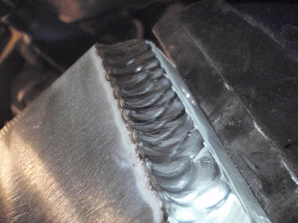
On my car the starter motor can't be fitted from below either. My engine mount brackets are fabricated from steel and pick up on all six of the tappings into the block with the mounting rubbers between them and the engine cossmember. The steering rack lies directly behind that, with the anti-roll bar behind that again immediately ahead of the sump.

My engine sits so far back in the car that the passenger/ navigator footwell area is alongside the sump, with the chassis rail itself not far from its side and the clutch slave cylinder behind it.

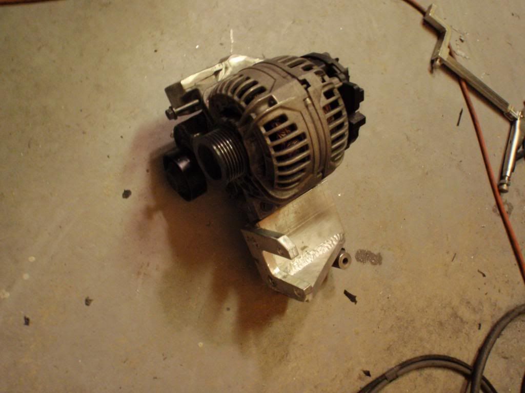
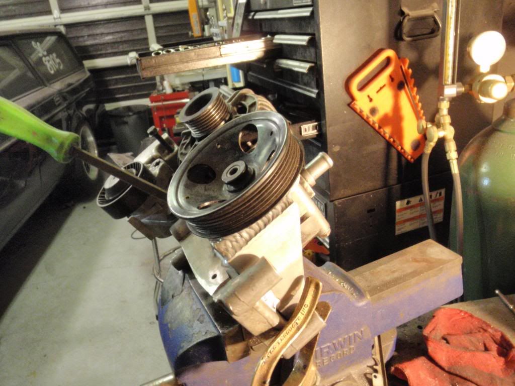
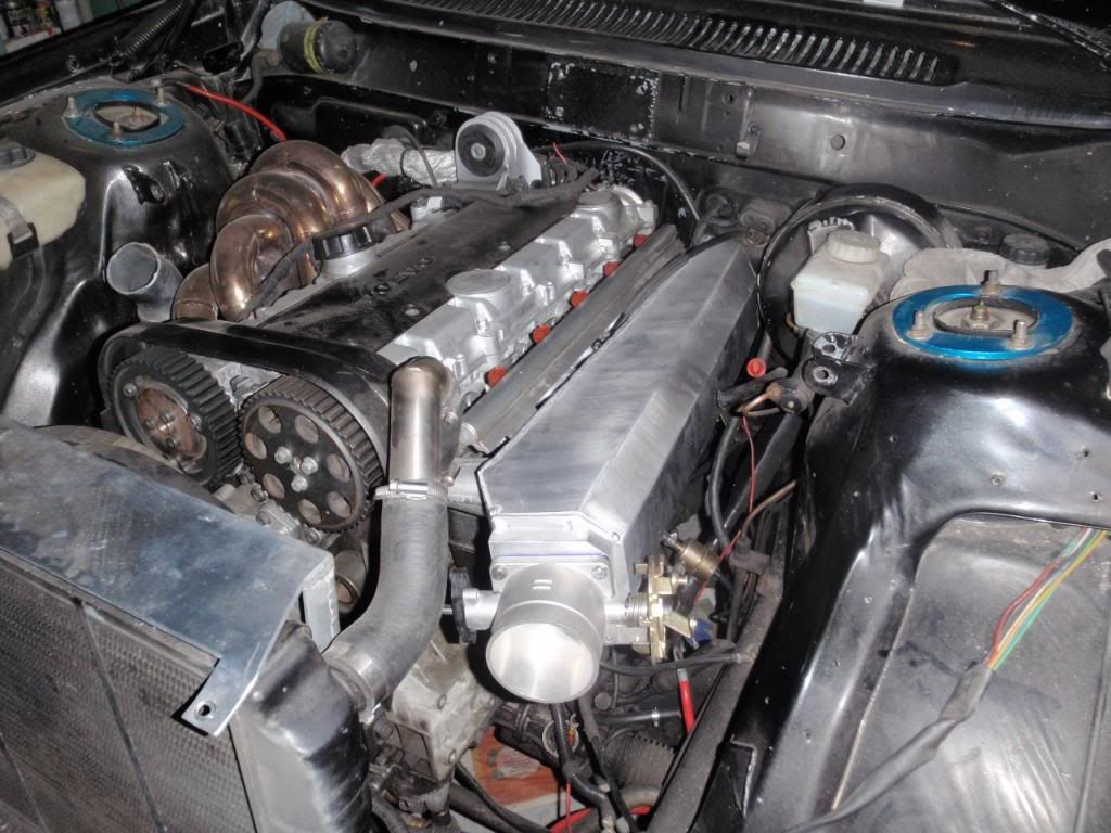
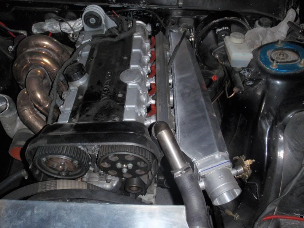
The currently fitted stock octopus manifold closes off almost all of the space to access from above, and even without a power steering pump in the way the breather and alternator (in addition to the mounting itself) denies any possibility of getting to the starter motor area from the front, never mind getting in to the manifold fixings. The large round octopus plenum with its lower brace to the engine mounting bracket in a simlar way to stock doesn't help the situation either.

After that last problem I decided that the manifold had to be changed to simplify servicing access, and I'd rather not disturb any of the fuel lines, connections, injectors, rail or wiring if possible to avoid any potential leaking seals and also help keep the service time down at meetings (this factor is less important at other times). The octopus manifold can't be removed without removing the strut brace either, which would be possible with a new one.

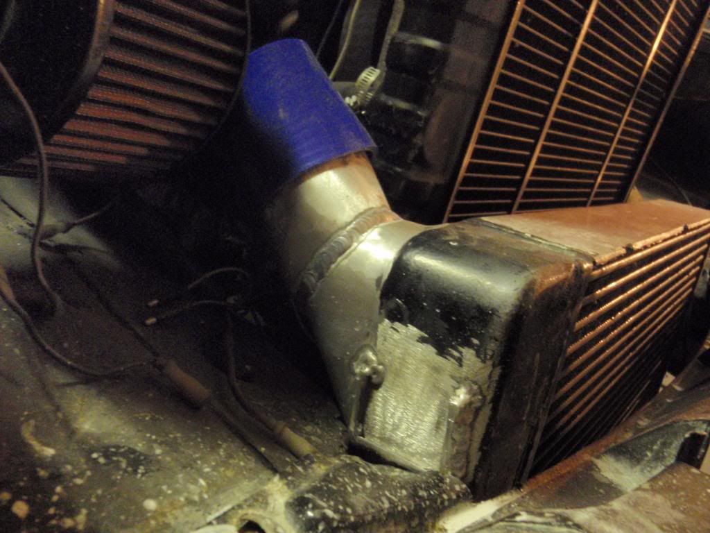
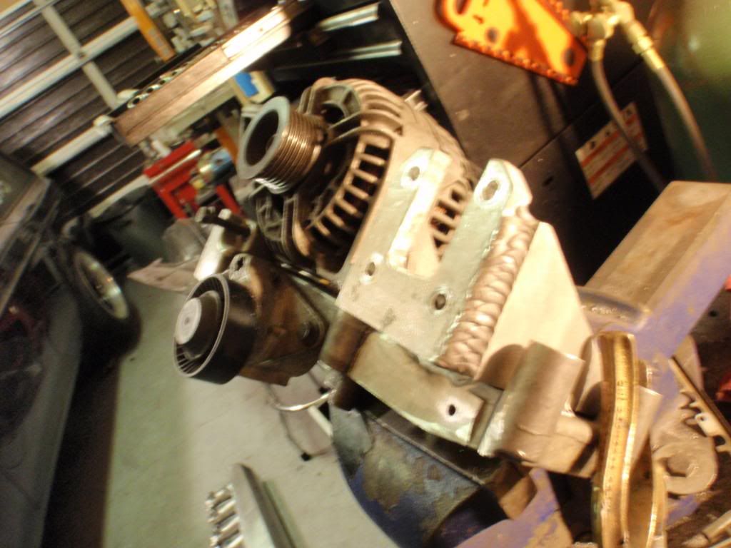
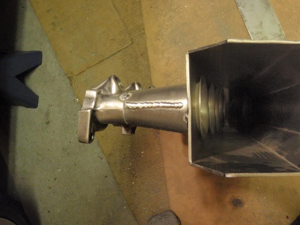
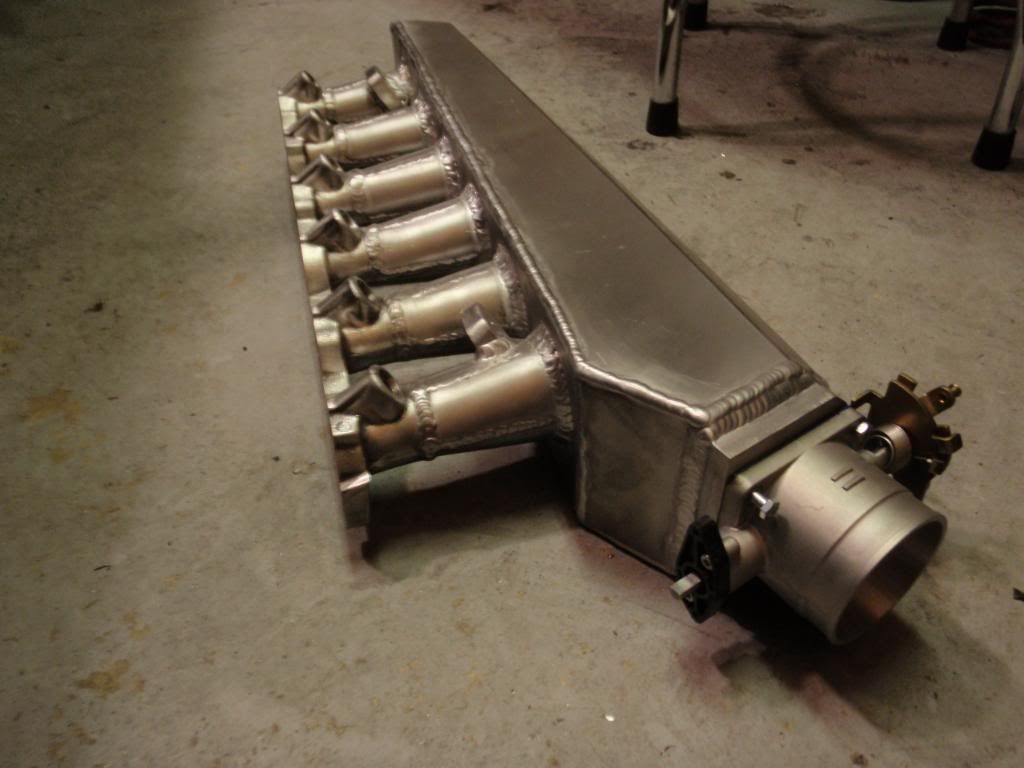
In making a new manifold I can take advantage of the stock rubbers to give me a point to easily split at, as well as changing to a front mounted throttle body to better suit connection to the intercooler, which should give me a really fast manifold removal time.

Your manifold, and the ones Nathan is currently fabricating for the redblock engines, is very similar to what I have in mind except for mounting it into the stock rubbers and bracing for both vibration and boost reasons back to the engine. There may not be any reason for anyone else to do this, but for me it seems like the best option.

I'd want to bracket the fuel pressure regulator to the 'fixed' part of the manifold, and look at making some quick release throttle cable arrangement that still incorporates the neccesary double return springs.

The resealing of these intake rubbers is a very good point though. Although they appear to be of the usual kind of synthetic material (unaffected by petrol) they do seem to suffer from hardening with age in the same way that I've seen happen on many similar motorcycle carburettor rubbers, and regular bending and flexing of them to fit the manifold runners probably won't do them any good as far as maintaining a seal under boost pressure. I'll start off with some brand new ones.

Still, a total of 7 jubilee clips, a couple of brace bracket bolts, a cable to unclip and possibly an intake tube to take off to remove the manifold should make servicing much easier than it is now!
 
Intake is done:
P1120333.jpg


Here's how the new cold side IC piping is done. About 375.6% better than how it was with the T6 intake.

P1120310.jpg


P1120311.jpg


In order to do that I had to modify my intercooler endtanks (that ironically I was explaining a while back how much i liked the design of. :rofl: They're even better now thought I think.

Basically they used to be 90 degrees to the core, but that just didn't allow me to get a 3" ic pipe up and into the throttle body.

So they started life like this:

P1010264.jpg


I cut em off and welded them on an angle.

Turbo side:
P1120281.jpg


(see intake pic above for intake side.)

The intercooler location is great now too. Most of the core is below the rad, so it and the rad both get dedicated flow. The bottom of the core ends up pretty much level with thew opening in the bottom of my bumper too, so I am going to make a duct that feeds air straight in, which should look sweet too.


Here is a pic of one of the welds that welds the runners to the stock cast manifold stub.
These pics are hard to take, but i tried anyways becuase I wanted to use it as an example to reinforce what 100% penetration looks like. IT LOOKS LIKE A WELD ON THE INSIDE TOO.
P1120287.jpg


The other thing I had to do was move the power steering pump down below the alternator so I made a nice beefy 1/2" cradle and jigged it up to be welded to the bottom of the accessory bracket. Not quite finished welding it yet but it's pretty much good to go:

P1120345.jpg


P1120344.jpg


P1120326.jpg


GIANT Weld (4 passes):

PB280227.jpg


Well I think that's it for now. Motor comes out this weekend and i finish getting the car ready for paint!

Hopefully a 2001 motor will go back in with H beam rods and an 0.70 turbine housing, 707 pressure plate, and an uprated fuel pump and injectors.

Wait till you guys see the color. :wtf::-D
 
Back
Top