• Hello Guest, welcome to the initial stages of our new platform!
    You can find some additional information about where we are in the process of migrating the board and setting up our new software here

    Thank you for being a part of our community!

Coolant Temp Sensor Issues and ECU Troubleshooting

mcschleg

New member
Joined
Jul 8, 2017
Location
North Dakota
Been Lurking,

The car in question: 93 Volvo 240 Estate B230f NA with Bosch LH2.4 and a -951 ECU

I have been having a redundant issue with my coolant temp sensor. To be clear I am referring to the 2 prong one under the #3 and #4 intake that goes to the ECU. As I sit right now I have replaced this little sucker 3 times now.

In my defense the first one came off a used engine that had sat exposed for some time and the second one I presumed to be broken from the supplier.

Every time these were replaced the car would appear to correct itself, ditch the codes associated with the coolant sensor that it had been showing and do fine... Until it would again, die unexpectedly and begin showing issues.

This is now happening again with the car throwing codes in both pin 2 and 6 on the OBD for CTS and is exhibiting the typical signs of a bad sensor.

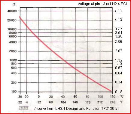
I just now tested the resistance on the sensor currently in the vehicle after warming it up to operating temp. This one was ordered from IPD less than a month ago and has probably 300ish miles on it. The sensor read back approx. 920ohms which seems correct given the temperature the engine was probably at for time of the test.

I have also just put in a new battery as I was getting codes for that and also wanted to eliminate that as a possible culprit on future troubleshooting.

My question here is now that I have a solid idea that the problem is not originating from the sensor what is my best course of action? Is it possible that I have a bad ECU? Maybe more likely, could it be bad wiring or grounding point? What are ways that I could test these theories? Is there a way to check the resistance/voltage between the ECU and the CTS plug? Is there a way to check the quality of the ECU?

Any information and help is appreciated.

Thank you
 
I doubt it's a bad ECU since it's throwing codes on both the LH and EZK ECU's.

What is the condition of the wires in the temp sensor connector? If the clear plastic around the contact is deteriorating it can cause a poor connection.

fullsize_3051.jpg


You can check the temp sensor values at the LH/EZK computer connectors. Here's a link to the '93 240 wiring greenbook.

https://ozvolvo.org/archive/?download=VGFsaWVzc2luIFBlbmZvdW5kIC0gVFAzMjM1Mi0xIDE5OTMgMjQwIFdpcmluZyBEaWFncmFtcy5wZGY=

The temp sensor grounds through the body of the sensor. Make sure there's no corrosion where the sensor contacts the head.
 
Last edited:
I doubt it's a bad ECU since it's throwing codes on both the LH and EZK ECU's.

What is the condition of the wires in the temp sensor connector? If the clear plastic around the contact is deteriorating it can cause a poor connection.

You can check the temp sensor values at the LH/EZK computer connectors. Here's a link to the '93 240 wiring greenbook.

https://www.ipdusa.com/uploads/images_products_slideshow/fullsize_3051.jpg

The temp sensor grounds through the body of the sensor. Make sure there's no corrosion where the sensor contacts the head.

That makes sense that it wouldn't be the ECU causing the fault. The condition of the wires and sensor connector seem to be just fine from visual inspection. No visible corrosion at the connector although I'm not sure what you mean by the clear plastic around the contact.

Is the link you posted meant to be for the green book? It just pulls up a picture from IPD for me.

Also, do the two wires coming out of the CTS run to the LH ECU exclusively? Or does one go to each ECU? Also how would you recommend testing the sensor values at the ECU? Bridge the contacts at the connector and then measure from the appropriate pins at the ECU?

Thanks in advance!
 
Sorry, link fixed.

The picture from iPd is of the wire for the temp sensor with the clear plastic cover. The grey plastic insulator that clips to the sensor depends on the clear plastic cover on the wires to hold them on the sensor.

open-uri20150625-18931-1h2q4kd.


The temp sensor is actually 2 sensors in one. One wire goes to each ECU. It'll become obvious when you see the wiring diagram.

Test the sensor values at the ECU's by using an ohm meter with the (-) wire connected to a known good ground and touching the ECU terminal from the side. Don't stick the probe in the socket.

TestingLH_ComputerHarness.jpg
 
Last edited:
To tailgate on hiperfauto, NEVER blindly trust those 25+ year old connectors as he shows above. The insulative sleeves crumble to dust, and if you push the connector on you "might" have a connection. I've had to blow the crumbs out of those connectors (open them up), then simply push each connector on the temp sender and I fill the cavity with clear RTV upon reassembly. A bad/loose connection will break your heart.
 
That terminated lead shown above is for the temp gauge, not the ECU temp sensor.

I do terminal drag tests with the proper tool to test for correct terminal tension. I use pins from old components as the special tool.

Do resistance tests as shown above.

Consider running a new circuit with NEW terminals at both ends. After a new sensor, and new circuits, all that's really left to try is another computer.

One member here chased this code until a new ECU fixed it.
 
Okay so photo dump but I have stumbled across some interesting things here while checking the wiring from the LH ECU. Hopefully this link works since I am not exactly sure how to post these pictures like you all have been doing.

https://1drv.ms/f/s!AvoIoQoVE1eXjo8e47ZBL2Fga_2e2Q

This link should send everyone to a folder of some pictures from me digging around in the ECU.

Their was a bit of confusion on the type of connector I have so I just took a picture of the one I have in the vehicle.

When I took the cover off the LH ECU I found that their had obviously been some hacking done. Spliced to the Blu-Red wire coming from pin 13 is a violet wire that leads to nowhere. The images should show how it was "insulated" and that the wire exits the harness and goes nowhere and was just dangling loosely behind the kick panel.

It should also be noted that I received no resistance or voltage data from my test of pin 13 it is likely I just did this wrong and will try again but I wanted to post these pictures.

To test I took the positive and plugged it into the side of pin 13 and the negative I plugged into pin 17 which is listed as a ground on the wiring diagram. I had the connector plugged into the coolant sensor during these tests and the battery connected. Not sure if I am doing this wrong but let me know as I am definitely not a wizard when it comes to electrical.

I was unable to check the EZK ECU since I wasnt able to figure out how to take that protective black cover off. Any tips on that would be appreciated but from a visual inspection it has not appeared to be tampered with.
 
Last edited:
Here is a LH2.4 wiring diagram, but it sucks:

http://s796.photobucket.com/user/ZVOLV/media/EFI Swap/lh24.jpg.html

Anyways, pin 13 on the LH box is the temp sensor and pin 2 on the EZK are the ones you need to check.

Obviously the last guy had a problem with that circuit and did some tampering. It looks like he added a "test wire" into the circuit so he could monitor the resistance/voltage.

I would cut and solder a fresh section of wire at the ECU.
First, I would check for continuity between that pin and the corresponding pin at the temp sensor terminal. Do the same with EZK pin 2 and the other terminal at the sensor. I would expect close to zero ohms. If they are both open, you gotta find the break, or run new wires.
 
Last edited:
Another suggestion I would like to make is don't remove the computer cover. You can remove the connectors to the computers. Remove the philips head screw and you can slide the cover off the wiring and connector. Then you can probe the side of the terminals for your checks.

It's also very important to check the resistance at three heat levels of the engine. On both the ezk and fuel ecu. Cold before start. Then at about 120 degrees warming up. Then fully up to temperature. You probably have a good sensor by now. But I've had bad sensors that go open circuit when hot. Makes the ecu think the engine is in the great north and dumps a bunch of fuel.
 
Last edited:
A replacement connector for the sensor should be easy to source. You could even snip one off a fuel injector from a donor car. Then run two new wires to the computers. Or just repair whatcha got- old Volvo stuff.
 
The temperature sensor is actually 2 sensors in one body - one pin goes to ECU, other pin goes to EZK, and the sensor grounds through the block. I've heard stories of grounding problems when using teflon tape on the sensor threads but since you're getting reasonable resistance measurements on the sensor pins to ground, it seems OK.

Since you're getting diag codes on both ECU and EZK, I'm suspicious that you have a bad ground. For my '93 LH 2.4 harness, there are 4 black ground wires going to 2 ring terminals (2 wires per ring terminal, but spliced together a few inches back in the harness). These bolt to the front/back of the intake manifold. Check that you have these ground wires+connections and that they look OK.

Pin 13 of the ECU should go directly to one of the 2 pins on the temperature sensor. If you have a helper and long meter probe wires, you can check the resistance end-to-end (should be ~0 ohms). Pin 5 of the ECU is the ground pin used for the sensor. It should go to one of the ground wires on the intake mainifold (again, ~0 ohms).

[BTW: resistance is always checked with power off -- you don't need to disconnect the battery, just key off is fine.]
 
Last edited:
I don't have test wires that are long enough to reach between the sensor and the ECU pins.

In that case when testing the resistance from the ECU's do you keep the coolant sensor plugged in and test resistance between pin 13 and the ground on pin 5 and testing the EZK on pin 2 and whatever it's ground is?
 
With sensor plugged in, the resistance between pin 13 and any ground should be the sensor resistance for the block temperature (900 or whatever ohms). pin 5 to any ground should be ~0 ohms. I think ECU connector pins 5,17,19,29, and EZK pin 20, should all go to ground. You can also use a clean chassis bolt, or the cigarette lighter outer metal sleeve for ground.

edit: you can also check the resistance of pin 13 to ground with the sensor unplugged -- should be open circuit unless the wire is shorted to something else between the engine and the ecu plug.
 
Last edited:
If I found that hack in a car I purchased, and could not ask the PO, I'd think about when the symptoms first appeared and try to determine if they were intermittent. Except for the workmanship, the wire splice looks like something I'd do to nail down a come-and-go trouble.

Then, I'd use the wire. Instead of making resistance checks, I'd connect a voltmeter to the wire and watch the response as the car was started cold and warmed up. I'd compare that voltage to the numbers in this curve, which would verify all of the things you would check with an ohmmeter, plus tell me whether the ECU was suspect.

ectCurve.jpg


Then if it wasn't apparent to me why the voltage readings didn't look like the chart, I'd make notes about what they are, at what time, and post the results on a board like this where others more familiar with that kind of stuff could make an analysis.
 
I'd go right for the kill and look for pins pressed back into the connector.

Use a long wire if you dont have long test leads. I use these 10ft leads. You want to know if there is excessive resistance in the circuit.

picture.php
 
Back
Top